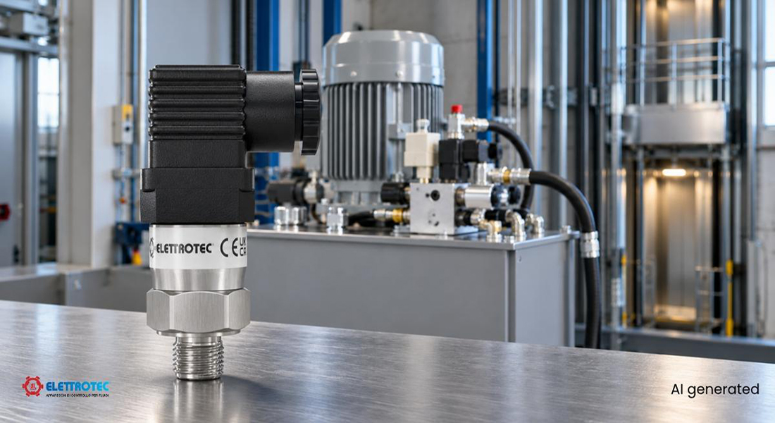
In hydraulic lifting platforms, the hydraulic power unit controls ascent and descent by regulating oil pressure and flow. The pressure switch converts that pressure into a signal for the control panel.
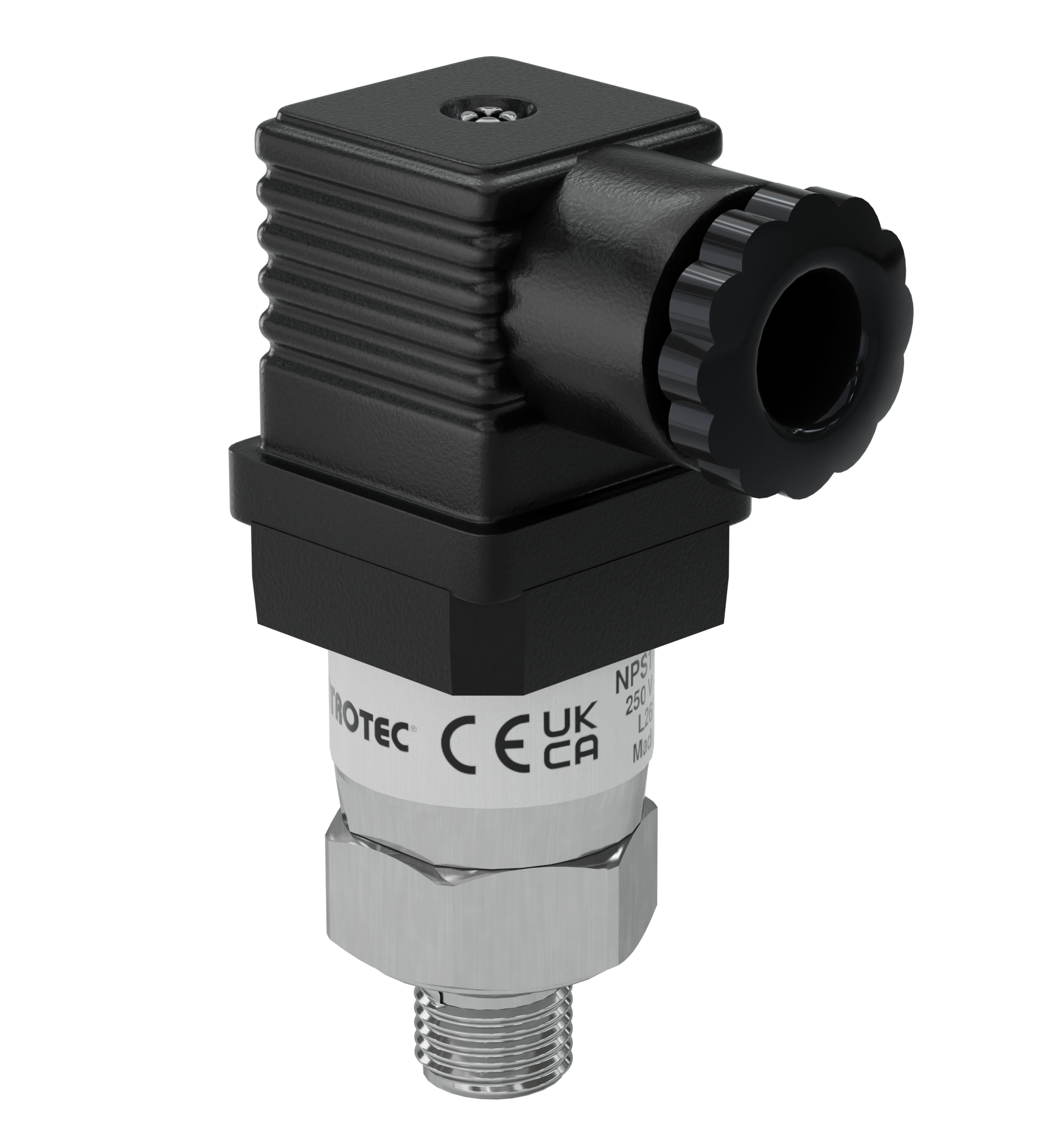
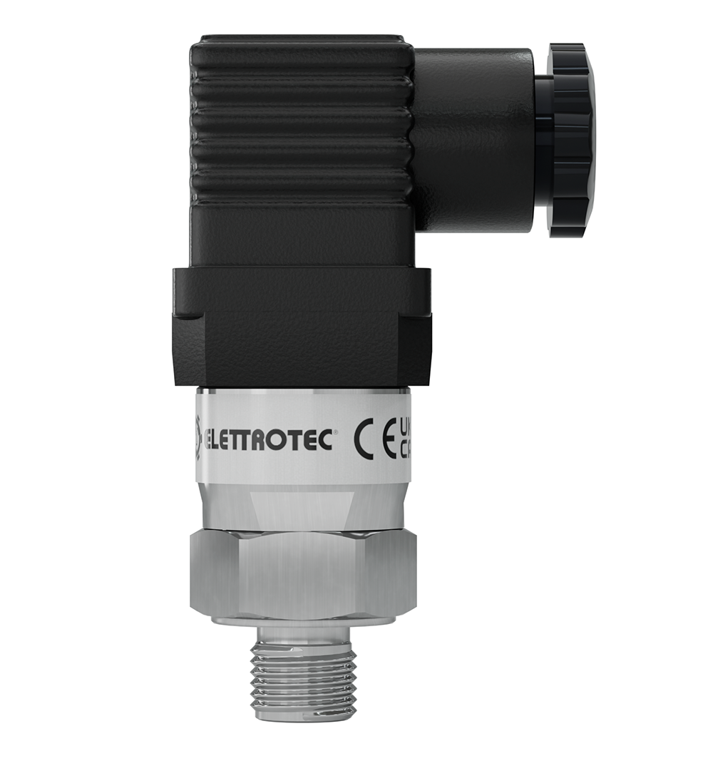
NPS is the new adjustable pressure switch developed by Elettrotec: a mechanical pressure switch with an SPDT changeover contact and fixed hysteresis, also designed for manufacturers of hydraulic power units and hydraulic lifting systems.
How the hydraulic power unit of a lifting platform works
During ascent, the electric motor drives the pump, which pressurizes the circuit. At start-up, a valve allows the oil to discharge; it then closes gradually and directs the flow towards the cylinder: the platform starts moving smoothly, without sudden movements or jolts. Once the desired height is reached, the pump stops and a check valve prevents oil from flowing back, helping to keep the platform in position.
During descent, the pump remains off. Movement is driven by the weight of the platform and its load, while a dedicated valve regulates the oil flowing out of the cylinder to ensure a smooth descent at a controlled speed.
Pressure monitoring in lifting platforms: the role of the pressure switch
In hydraulic lifts, the pressure switch is installed on the delivery line connected to the cylinder. From this position, it monitors circuit pressure both during ascent and when the platform must remain at the height reached with the pump switched off.
When the pressure reaches the set threshold, the contact switches and the control panel receives a signal that can be used for system management and safety. How this signal is used depends on the control logic; the pressure switch is responsible for detecting when the threshold is reached or exceeded.
In some applications, two pressure switches are installed to increase the redundancy of the control system, potentially with contacts operating in complementary modes: one normally open and one normally closed, depending on the safety logic adopted.
NPS: mechanical pressure switch with SPDT changeover contact
NPS belongs to the range of Elettrotec mechanical pressure switches. Its body has a 24 mm hexagon, 1/8 and 1/4 threaded connections in tapered BSPT or parallel BSPP versions, and an IP65 protection rating. These specifications make it possible to assess dimensions, connections and wiring requirements on the hydraulic power unit during the design phase.
The SPDT changeover contact (Single Pole Double Throw) has one common terminal and two paths, normally open and normally closed: when switching occurs, the common terminal moves from one to the other. The designer of the hydraulic power unit can therefore connect the contact that matches the control panel logic without changing the device. In a redundant configuration, for example, two NPS switches can be wired, one using the normally open contact and the other using the normally closed contact.
The COM, NO and NC terminals are available in versions with a DIN 43650 connection and a DIN connector with an M12 adapter. Versions with a Deutsch DT04-2P connector, however, are supplied as either normally open or normally closed: in this case, the contact type must be specified when ordering.
Fixed hysteresis and adjustable switching threshold
The switching and reset points of a pressure switch are separated by a differential, known as hysteresis. When calibrated for rising pressure, the device switches when the pressure reaches the set threshold and returns to its initial state when the pressure falls to the reset value.
This separation limits repeated switching when the pressure fluctuates near the threshold, provided the fluctuations remain within the differential. NPS has fixed hysteresis: the designer selects and sets the switching point without having to adjust the differential separately.
The result is a straightforward configuration for hydraulic power units that require this behaviour. When selecting a model, it is important to check that its specified differential is compatible with the pressure variations in the circuit and the desired reset conditions.
How to choose the NPS adjustable pressure switch for a hydraulic power unit
NPS offers six adjustment ranges. The choice depends on the threshold to be detected, the permitted tolerances and the pressures present in the system.
| Model | Adjustment range |
| NPS 2 | 0.2–2 bar |
| NPS 10 | 1–10 bar |
| NPS 50 | 10–50 bar |
| NPS 100 | 10–100 bar |
| NPS 150 | 30–150 bar |
| NPS 300 | 50–300 bar |
The maximum permissible static pressure must be distinguished from the adjustment range: it is 300 bar for diaphragm versions and 600 bar for steel-piston versions. These values describe the component’s static pressure resistance, not a switching threshold that can be set on every model.
The body material and the diaphragm or seal must also be selected according to the fluid and temperature. For example, the datasheet specifies a range of −5 to +60 °C for NBR and −25 to +125 °C for HNBR. Temperature limits therefore depend on the selected version.
Settings for rising or falling pressure at the requested value are available, as well as an optional water-hammer damper. The electrical characteristics of the connected circuit must also be checked against the specified contact ratings.
Define the NPS configuration for your system
When selecting a pressure switch for hydraulic power units, it is useful to start with a few design parameters: switching pressure, calibration direction, maximum circuit pressure, fluid, temperature and required electrical connection.
If you design, manufacture or maintain lifting platforms or hydraulic lifts, contact our technical department to assess NPS. By comparing these data with the available configurations, we can identify the version that best suits your hydraulic power unit.